Steel fabrication accuracy starts before a saw, drill, laser, plasma table, or welding system touches material. Accuracy starts with information.
A fabricated member might contain dozens of coordinated details. Length, section size, grade, holes, slots, copes, plates, stiffeners, welds, bolts, camber, orientation, finish, piece marks, and connection geometry all need to agree with the approved design. Every item also needs to relate correctly to nearby steel, concrete, equipment, architectural elements, and field installation requirements.
Traditional drawings remain essential, but complex projects benefit from a coordinated three-dimensional working environment. 3D modeling for steel fabrication gives detailers and project teams a clearer way to develop, review, and communicate the information behind each part and assembly.
Mid-City Steel uses Tekla Structures and Tekla PowerFab to connect detailing with fabrication and production. The value does not come from software alone. The value comes from experienced people using model-based information to identify conflicts, review constructability, control revisions, guide automated equipment, and support better fit-up in the field.
Mid-City Steel describes this connected process as a way to identify issues earlier, validate connection details, improve clash detection, and produce accurate information for the shop and field.
A 3D Model Is More Than a Picture
A rendering shows what a project might look like. A fabrication model contains information required to build the steel.
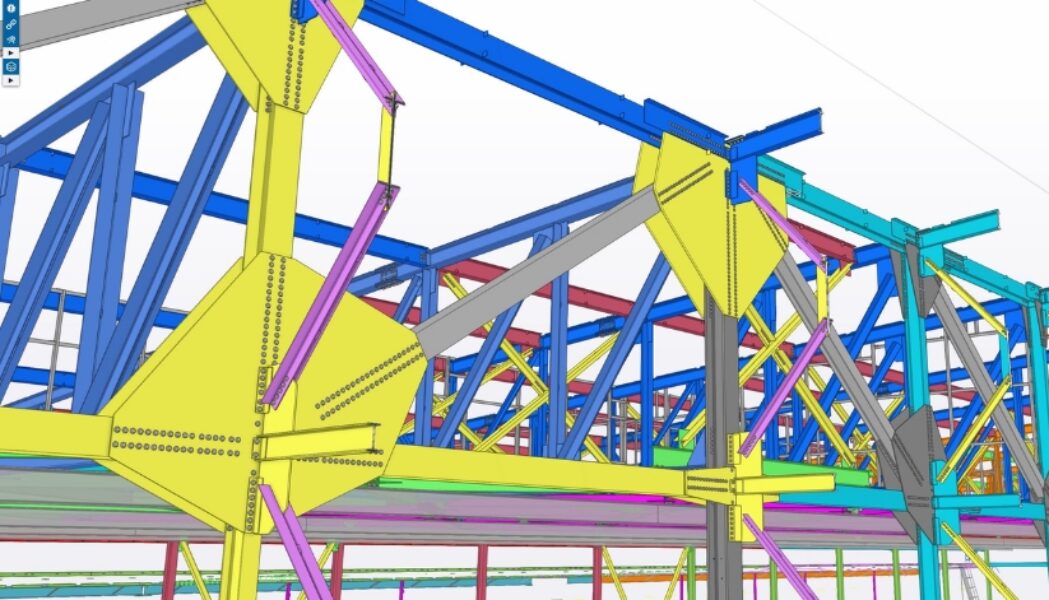
Each modeled object carries geometry and related data. A beam has a size, grade, length, position, and orientation. Connection components have dimensions and locations. Bolts have diameters, patterns, and spacing. Welds have types, sizes, and extents. Plates have thicknesses, contours, holes, and material properties. Assemblies receive piece marks and relationships used for drawings, reports, purchasing, and production.
This information-rich environment helps a detailer understand the whole assembly instead of interpreting isolated lines on separate views. Rotating the model exposes conditions hidden in a plan or elevation. Section views show tight spaces. Filters isolate phases, grids, elevations, sequences, materials, or finishes. Model views help project teams discuss a specific condition with less ambiguity.
The model still needs careful development. Software does not decide whether a detail follows the contract documents, satisfies the engineer’s intent, supports fabrication, or fits the erection plan. Experienced detailers build and review the model. Project managers control information and approvals. Fabricators provide practical input. Quality personnel verify physical work. The model gives each group a stronger shared reference.
Detailing Translates Design Into Fabrication Information
Structural design documents define the framing system and design requirements. Fabrication documents convert those requirements into part-level and assembly-level instructions for the shop and field.
This translation involves far more than drawing a beam between two points. The detailer accounts for connection design information, edge distances, bolt spacing, weld access, plate geometry, member orientation, elevations, clearances, camber, shipping splits, erection marks, finishes, and interactions with surrounding work.
A small discrepancy at this stage spreads quickly. One incorrect elevation affects several connections. One outdated member size changes plates, holes, bolts, welds, material orders, CNC files, and drawings. A conflicting grid dimension might affect an entire line of steel.
3D modeling for steel fabrication helps detailers see related conditions together. A change to one object updates associated views and data when the model is managed correctly. Reports and drawings come from the same underlying model instead of separate manual sources. This reduces repeated data entry and gives the team a better chance to identify inconsistencies before release.
The result still depends on disciplined checking. Model-based work does not remove review. A strong detailing process includes internal checks, controlled submittals, design-team review, RFI resolution, revision tracking, and formal release for fabrication.
Clash Detection Finds Physical Conflicts Earlier
A clash occurs when two objects occupy the same space or violate a required clearance. In steel work, a clash might involve two connections, a beam and duct, a brace and pipe, a stair and wall, a platform and equipment, or a bolt location blocked by another component.
Some clashes are obvious in a model. Others involve installation space rather than direct overlap. A bolt might fit geometrically but lack room for a wrench. A weld might exist on the drawing but sit behind a plate or too close to another member for practical access. A pipe might clear the steel but leave no room for insulation. A maintenance path might meet code width on plan while a handrail return narrows the actual opening.
Tekla Structures includes clash-checking tools for reviewing interactions among native model parts and reference model objects. Those tools help teams locate overlaps and minimum-distance concerns for review. The software reports conditions. People still decide whether each condition represents a true conflict, an acceptable overlap, or a design issue requiring action.
Clash detection delivers the greatest value when coordination happens early and includes useful reference models. Structural steel, concrete, mechanical systems, architectural elements, equipment, and miscellaneous metals all need current information. A perfect steel model cannot reveal a conflict with missing or outdated outside data.
When teams coordinate current models, many field conflicts move into a digital review. Resolving a brace-and-duct conflict in the model usually costs less than cutting, moving, redesigning, or delaying work after both systems reach the jobsite.
Constructability Review Looks Beyond Clashes
A clash-free model does not automatically equal a buildable project. Constructability review asks a broader question. Does the modeled solution support efficient fabrication, handling, shipping, erection, access, inspection, and final use?
Fabrication concerns include machine capacity, cut geometry, tooling access, weld position, fit-up, distortion, assembly size, material availability, coating access, and inspection. A detail might fit in the model while creating difficult shop work. Experienced fabricators help identify a simpler connection, better assembly split, improved weld sequence, or more practical plate geometry for engineering review.
Handling and shipping add more questions. Will the completed assembly fit through the shop and coating area? Does the assembly fit on a trailer within route restrictions? Where will rigging attach? Does the load need temporary bracing? Will an exposed finish remain protected? Would a field splice reduce transportation risk?
Erection review considers crane picks, temporary stability, bolt and weld access, connection order, tolerance, and work by other trades. A connection assembled easily on a screen might require an ironworker to reach behind a member with limited access. A stair landing might need installation before adjacent framing closes the opening. A large platform might save field labor but exceed crane or access limits.
3D modeling creates a useful environment for these conversations. The project team looks at the same geometry, marks up the same area, and evaluates options with clearer context. The model supports judgment. The model does not replace judgment.
Connection Validation Supports Better Fit-Up
Field fit-up depends on many small relationships. Hole patterns need to align. Bearing surfaces need the intended elevation. Columns need correct base geometry. Beams need correct length and end preparation. Bracing needs connection points matching actual framing. Stairs and rails need dimensions coordinating with slabs, walls, and finishes.
The model lets detailers assemble connections digitally before fabrication. Components join in their intended position. Bolt groups align across connected pieces. Plates meet member faces. Copes clear flanges. Stiffeners avoid conflicts. Welds receive accessible locations. Shop and field connection elements remain visible as a complete system.
This process helps reveal errors difficult to spot in separate two-dimensional views. A rotated plate, mirrored hole pattern, reversed clip angle, wrong work point, or missed skew becomes easier to see in context.
Fit-up also involves tolerances. Steel, concrete, masonry, equipment, and architectural finishes each follow different tolerances and field conditions. The model should reflect known interfaces and allow appropriate adjustment where the design permits. Slots, shims, field welds, bearing details, and adjustable connections often manage real-world variation. These features need engineering direction and deliberate detailing, not informal field correction.
Accurate modeling reduces avoidable discrepancies. Quality control still verifies fabricated dimensions, welds, material, and finish before shipment. Model accuracy and shop inspection support one another.
Connected Data Reduces Manual Handoffs
A major advantage of model-based fabrication comes from using model information across several project phases. Re-entering the same data into separate systems creates opportunities for transcription errors, missed revisions, and inconsistent records.
Tekla Structures supports detailed modeling and drawing production. Tekla PowerFab supports fabrication management activities such as estimating, purchasing, inventory, production, and shipping workflows. Trimble’s Tekla PowerFab Connector links detailers and fabricators through a coordinated exchange of model, purchasing, status, change, and submittal information. Trimble describes the workflow as a way to reduce manual fixes, data-transfer conflicts, fabrication delays, wasted material, and budget pressure.
For a fabricator, connected information supports several practical steps. An advance bill of material helps purchasing evaluate quantities before every shop drawing reaches completion. Released model information supports CNC and automated processing. Piece marks connect drawings, material, production status, quality records, staging, and shipping. Revision data helps teams identify work affected by a design change.
A connected workflow also improves visibility. Project managers see which packages remain in detailing, approval, purchasing, fabrication, coatings, or shipping. Production teams receive current information. Shipping teams understand completed pieces and delivery priorities. Field teams receive drawings and status tied to the same project structure.
Connected does not mean automatic or uncontrolled. Each handoff still needs defined approval and release rules. Teams need to know whether information is preliminary, submitted, approved, revised, or released for fabrication. Strong status controls prevent early data from becoming unintended production direction.
Revision Control Protects Work Already in Motion
Steel projects change. Engineers issue clarifications. Architects revise openings. Equipment vendors update loads or dimensions. Contractors change sequences. Field conditions require adjustment.
The impact of a revision depends on timing. A model change before purchasing has one cost. The same change after material processing, assembly, coating, or shipment carries a different impact.
Model-based revision control helps teams compare current and prior conditions. Changed objects become easier to identify. Detailers update affected drawings and reports. Project managers review released packages. Purchasing checks material impact. Production control identifies pieces already started or completed.
The model provides a central place to understand the geometry of the change, but successful change management reaches beyond the model. CNC files, bills of material, work orders, inspection documents, coating instructions, shipping lists, and field drawings also need current information.
This is where Tekla Structures and Tekla PowerFab provide more value together than either platform provides alone. One supports detailed project information. The other connects information to fabrication management. Mid-City Steel’s technology approach focuses on controlled revisions, piece-level status, production updates, and alignment from the shop floor to the field.
Model-Driven Fabrication Supports Automation
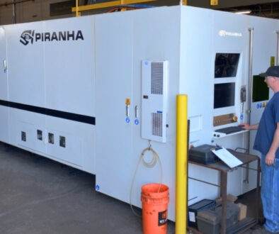
Modern fabrication equipment often uses digital data generated from the model. Saw and drill lines process member lengths and holes. Robotic structural processing systems produce copes, slots, markings, and cuts. Laser and plasma tables cut plate contours. Robotic welding systems use model-driven information on suitable work.
Direct data flow reduces manual layout and repeated measurement. Automated systems produce repeatable features when the model, programming, setup, tooling, and material condition are correct.
The phrase ‘when the model is correct’ deserves emphasis. Automation repeats information efficiently. One incorrect hole location sent to automated equipment might affect many pieces before someone recognizes the pattern. Experienced operators verify programs, orientation, material, tooling, and first-piece results. Quality personnel inspect fabricated work against approved requirements.
Model-driven fabrication works best inside a controlled system. Detailers release verified data. Production teams use current files. Operators monitor equipment. Quality checks occur at planned stages. Revision controls prevent obsolete information from reaching the machine.
Mid-City Steel combines Tekla-based workflows with saw and drill systems, multi-axis processing, laser cutting, plasma cutting, press brake forming, robotic welding, automated shot blasting, and controlled coating processes. The technology supports accuracy and production flow while experienced people remain responsible for decisions and verification.
3D Models Improve Communication Across Teams
Different project participants read information in different ways. Engineers focus on design intent and load paths. Detailers focus on connections and fabrication documents. Fabricators focus on parts and assemblies. Erectors focus on picks, access, stability, and sequence. Contractors focus on coordination and schedule. Owners focus on performance, budget, and risk.
A model gives those groups a common visual reference. During a coordination meeting, the team isolates an area, rotates the view, checks dimensions, and discusses a specific condition. This often produces clearer decisions than exchanging marked-up screenshots without shared context.
Model views also support planning beyond the steel package. Teams review equipment clearances, access platforms, openings, maintenance zones, architectural interfaces, and erection stages. A sequence model helps explain which steel arrives and installs first. A color-coded status view helps communicate progress.
The model should support communication, not overwhelm participants. Useful meetings focus on decisions. Model views need clear scope. Markups need ownership. Open issues need deadlines. A detailed model creates value only when the project team uses the information to move work forward.
What 3D Modeling Does Not Solve
3D modeling improves visibility and information control, but no software removes incomplete design, delayed decisions, unclear scope, or poor communication.
An outdated reference model produces outdated coordination. Missing equipment geometry hides conflicts. Unresolved RFIs hold up detailing. Late approvals compress fabrication. Incorrect model input produces incorrect output. A beautifully rendered connection still fails when the underlying requirement is wrong.
Project teams should treat the model as part of a managed process. Define model uses early. Establish who provides each reference model and when. Set coordination milestones. Clarify approval authority. Track open issues. Control revisions. Confirm fabrication release status.
Experienced people remain essential at every step. Detailers interpret documents. Engineers approve design decisions. Project managers coordinate timing. Operators understand equipment and material. Inspectors verify work. Erectors bring field knowledge.
Technology gives those people stronger tools. The project still succeeds through disciplined execution.
Better Digital Information Supports Better Field Results
The purpose of 3D modeling for steel fabrication is not a more impressive screen image. The purpose is steel arriving at the jobsite with fewer preventable questions.
A coordinated model supports accurate shop drawings, clear erection drawings, reliable part data, stronger clash review, better constructability decisions, controlled revisions, model-driven fabrication, and useful piece tracking. Those improvements support field fit-up and installation efficiency. No model guarantees a perfect fit. Field conditions, tolerances, changes, and human error remain part of construction. A connected model-based process reduces avoidable risk by finding more issues before material reaches the shop or site.
Mid-City Steel combines Tekla Structures, Tekla PowerFab, advanced fabrication systems, and experienced steel professionals to connect detailing directly to production. The approach keeps technology focused on project outcomes. Better information. Better coordination. More controlled fabrication.
Planning a structural or miscellaneous steel project with complex geometry, tight tolerances, demanding coordination, or an aggressive schedule? Talk with Mid-City Steel about detailing, modeling, fabrication, and production planning.